LTI++by SimuQuest
LTI++ is a toolset for rapidly generating linear design models and for rapidly designing linear time-invariant (LTI) controllers for feedback control applications in spark ignition engines.
When do I need LTI++
LTI++ is a powerful tool to support the analysis, synthesis and validation of linear model-based feedback control systems for a variety of engine control applications such as idle speed control, wide-range A/F-ratio control, EGR-ratio control, etc. The tool is designed to alleviate efforts in every aspect of practical model-based engine control design. LTI++ also has an excellent tutorial potential. Its ease of use and its seamless integration with Matlab/Simulink, make it a perfect training vehicle for people who seek to gain practical insight and intuition for the fundamentals of model-based control system development.
How does LTI++ work
 LTI++ is a set of tools that span the entire spectrum of practical engine control design, i.e., the generation of linear design models, the analytical analysis of plant and closed-loop control system properties, the simulation of plant and control system models, and the validation of closed-loop controllers in terms of stable and robust performance. The tool complements the nonlinear engine model toolset Enginuity. Fully calibrated Enginuity models are used to automatically generate linear engine plant models. These are linear models that capture the dynamic behavior of the target engine in the vicinity of a nominal operating point. The user simply specifies the nominal operating conditions and the tool readily generates the corresponding linear base model. LTI++ is a set of tools that span the entire spectrum of practical engine control design, i.e., the generation of linear design models, the analytical analysis of plant and closed-loop control system properties, the simulation of plant and control system models, and the validation of closed-loop controllers in terms of stable and robust performance. The tool complements the nonlinear engine model toolset Enginuity. Fully calibrated Enginuity models are used to automatically generate linear engine plant models. These are linear models that capture the dynamic behavior of the target engine in the vicinity of a nominal operating point. The user simply specifies the nominal operating conditions and the tool readily generates the corresponding linear base model.
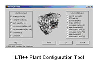 The linear base model maps the dynamics from all available engine input signals to all output signals, e.g., from throttle position, fuel factor, spark angle, cam phase angle, etc., on the input side to engine speed, engine torque, A/F-ratio, residual gas fraction, etc., on the output side. Once a linear base model for a given target engine is generated the user can configure the plant inputs and outputs according to the control problem at hand. For example, for multi-variable idle-speed control, one would select throttle position (or idle actuator position) and spark angle as the relevant inputs and engine speed as the relevant output. The linear base model maps the dynamics from all available engine input signals to all output signals, e.g., from throttle position, fuel factor, spark angle, cam phase angle, etc., on the input side to engine speed, engine torque, A/F-ratio, residual gas fraction, etc., on the output side. Once a linear base model for a given target engine is generated the user can configure the plant inputs and outputs according to the control problem at hand. For example, for multi-variable idle-speed control, one would select throttle position (or idle actuator position) and spark angle as the relevant inputs and engine speed as the relevant output.
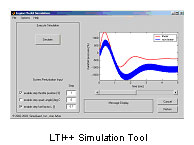 A dedicated simulation tool facilitates the analysis of the transient behavior of the plant model and/or the validation of the transient performance of the plant model vs. the nonlinear model from which it had been derived. A dedicated simulation tool facilitates the analysis of the transient behavior of the plant model and/or the validation of the transient performance of the plant model vs. the nonlinear model from which it had been derived.
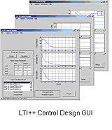
LTI++ currently supports two different control synthesis methods, PID design and H¥ optimal control design.
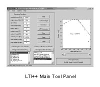
Both methods are fully GUI supported. The tool facilitates rapid controller design, display of the frequency domain properties of relevant system transfer functions and rapid validation of the time domain performance of the closed-loop control system both with the nominal plant model and also with plant models that deviate from nominal operating conditions.
LTI++ Paradigm
 The following is a synopsis of virtual control algorithm design and is meant to illustrate the power of the LTI++ toolset jointly with the UniPhi architecture tool for rapid control system prototyping. From a base Enginuity model derive a linearized plant model within LTI++ and select relevant inputs (e.g., throttle position, spark angle, etc.) and outputs (e.g., engine speed) for the control problem at hand. The following is a synopsis of virtual control algorithm design and is meant to illustrate the power of the LTI++ toolset jointly with the UniPhi architecture tool for rapid control system prototyping. From a base Enginuity model derive a linearized plant model within LTI++ and select relevant inputs (e.g., throttle position, spark angle, etc.) and outputs (e.g., engine speed) for the control problem at hand.
Design a feedback controller (PID or H¥) for the selected plant and save the controller transfer function in a file. To evaluate the controller in virtual reality devise a base engine control strategy for open-loop spark and fuel control within UniPhi. Allow for additive or multiplicative feedback corrections in the open-loop control signals. Embed the feedback controller in terms of a state-space block within the base engine control strategy of UniPhi. Configure UniPhi for a simulation target and simulate the controller in the loop with the Enginuity model.
Assess the control performance and adjust the controller design if necessary. The described process does not require any experimental testing, neither for the purpose of model development nor for the purpose of controller validation. Yet, due to the accuracy of Enginuity models across the entire engine operating-envelope and due to the architecture design paradigms incorporated in UniPhi, control systems that have been validated in virtual reality readily work on the target hardware application.
|
|
|
|