Structural Dynamics Toolboxde SDTools
Structural Dynamics Toolbox (SDT) mejoras las capacidades básicas de MATLAB en lo que hace referencia a los controles y el procesado de señal, mediante extensiones ligadas al modelado general de elementos finitos 3D, al análisis modal experimental y a la correlación prueba/análisis.
Overview
For analysis, the SDT provides a general finite element architecture that can be used in all fields and a range of specialized solvers to create models used to study vibration problems. Interfaces with popular FEM codes and Graphical User Interface (GUI) visualization tools let you build on the MATLAB/SDT ease of use to pre-/post-process computations done using SDT or other codes. Key compiled functions allow treatment of large models. For test, the SDT provides all the modal analysis tools needed to exploit frequency domain measurements. GUIs are provided for visualization of responses, frequency domain identification, animation of modes and operational deflection shapes, topological correlation, and test/analysis correlation criteria.

Key Features for Analysis
- General 3-D Finite Element Modelling with an open architecture allowing easy user developments
- Pre-processing and visualization of FEM computations
- Model reduction,substructuring and system model building
- Physical parametrization of FEM models for optimization or updating
Key Features for Tests
- GUI based visualization of test data and frequency domain identification
- Animation of test and FEM results
- Topology correlation and test/analysis criteria
- Import/export routines for popular test and FEM model formats
- Specialized routines to go from test and finite element models to state-space and other system dynamics formats
Finite Element Modelling
An open source base library
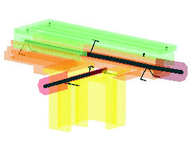
The general purpose FEM environment of the SDT is now developped as part of the OpenFEM library, which provides elements (beam, shells, volumes, ...), matrix and load assembly tools, stress computations. The open specification of data structures and element function services allows integration of user developments in the pre-/post-processors and solution methods.
Solvers
The SDT provides optimized solutions for:
- static response to loading cases,
- partial eigenvalue solutions,
- model reduction (Guyan,Craig-Bampton and MacNeal...) for Component Mode Synthesis or state-space model generation,
- creation of state-space models for easy incorporation in the Control Toolbox or SIMULINK®
- computation of frequency response functions.
SDT 5.0 introduces the notion of cases to handle complex definitions of loads, boundary conditions, constraints, physical parametrization, etc. Further work on the optimization now allows reasonable handling of models up to 500,000 DOFs.
 Visualization Visualization
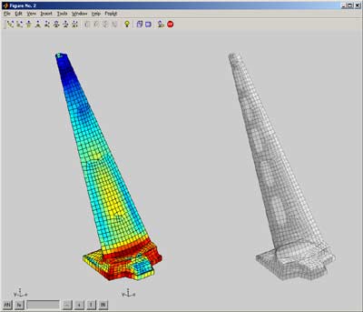
The object oriented GUI allows visualization and animation of FEM and test. You can combine 3-D surface, wire-frame, or sensor objects in the nominal or deformed configuration, redefine new deformations or sensor configurations for the current structure, scan through a set of deformations, efficiently zoom with the mouse, control amplification, animate real, complex, or color shapes, show selected substructures, rotate the structure, and more.
Mesh manipulations
The femesh user interface enables the creation and extensive manipulations of finite element models. Commands allow element and node selection, translation, extrusion, repetition, revolution, mesh refinement... All these operations are compatible with both SDT and user defined elements and are used extensively for part visualization, parameterization, etc.
 Import/export Import/export
While femesh handles simple geometries, industrial models need general 3-D meshers that are only available in full fledged CAD systems. SDT FEMLINK thus provides interfaces with popular formats : NASTRAN, ANSYS, Universal File Format, PERMAS,...
Physical Parametrization
The upcom function allows easy manipulations of large parametrized models. Physical parameter variations (modulus, density, thickness...) can be associated with arbitrary element set selections. Model matrices, modeshapes,modeshape sensitivities,and frequency responses can be easily computed at each design point. The main applications of this interface are optimization and finite element model updating based on experimental data.
Experimental Modal Analysis
Frequency domain identification
A complete methodology to solve the frequency domain output error problem is proposed. This includes advanced single pole MIMO estimation and model tuning strategies which fully replace traditional procedures based on stabilization diagrams. This iterative approach is both more intuitive and very often more accurate than methods found in other modal analysis packages. Identification functions include treatment of MIMO models, multiple modes, real and complex modes, reciprocity, non-proportional damping models, as well as transformations between pole/residue, state-space, second-order mass, damping, stiffness, or polynomial forms.

Data Visualization and Analysis
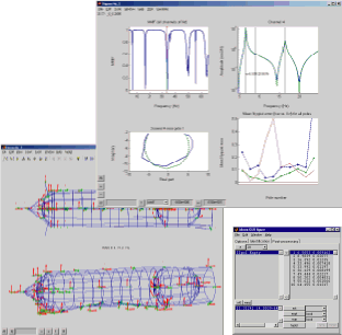
The iicom, iiplot graphical user interface for the visualization of Multiple-Input Multiple-Output (MIMO) datasets easily generates Bode plots, Nyquist plots, Multivariate Mode Indicator Function, complex residue phase spread, pole location, etc. Once the plots generated,simple mouse/key movements let you scan through the data set,get information on certain points, zoom, etc. Version 4 introduces new plots, context menus,and optimized speed.
Model format conversion
The SDT provides a full set of two way model format conversion functions for full order finite element models, truncated normal mode nor models traditionally used in structural dynamics, frequency response xf, pole/residue res, state space ss, polynomial transfer function tf. Transformations from frequency response xf to res, ss and nor are supported system identification phases. Transformations from xf and nor formats to full order finite element parameters correspond to finite element update problems. Other transformations have direct analytical expressions and are supported with an emphasis on providing numerically efficient solutions.
Test/Analysis Correlation
The objective of the SDT in this area is to provide flexible access to all standard and many advanced tools to correlate experimental modal analysis results with industrial size finite element models.
Topology correlation
SDT visualization and analysis tools support general sensor setups with mixed translation/rotation measurements, non orthogonal sensors, laser measurements, non-coincident test and FEM nodes,... fe_sens provides sensor placement algorithms and automated and/or directed test/FEM node linking with support of different test/FEM coordinate systems, mixed translation/rotation sensors,and rotation interpolation for non- coincident nodes of volume models. The use of observability equations gives access to all correlation and shape expansion methods with no need to modify the FEM model (a unique and very time saving feature).
Shape expansion
Expansion methods for arbitrary sensor configurations are modal, static, dynamic, and the advanced minimum residual with and without measurement error. The use of FEM model reduction lifts the computational restriction on using advanced methods.
Correlation criteria
The new ii_mac GUI supports the COMAC, MAC, MACCO, POC, and relative error criteria,with standard graphical and tabular output, automated mode pairing, computation and use of reduced mass in all the criteria. Functionality is accessed either though menus or through the SDT handle object associated with the figure.
|

