3DTransVidia - SolidWorksby Capvidia
3DTransVidia - SolidWorks combines all advantages of a stand-alone application with integrated SW Add-in. 3D TransVidia-SW extends SolidWorks with a modular multi-functional Front-End for data import, feature based translation, reverse engineering, offset and surface approximation.
 3DTransVidia-SolidWorks combines all advantages of a stand-alone application with integrated SW Add-in. The link with SolidWorks is established over the SW API operating on a common memory structure providing the most efficient and reliable data transfer. 3DTransVidia-SW extends SolidWorks with a modular multi-functional Front-End for data import, feature based translation, reverse engineering, offset and surface approximation. 3DTransVidia-SolidWorks combines all advantages of a stand-alone application with integrated SW Add-in. The link with SolidWorks is established over the SW API operating on a common memory structure providing the most efficient and reliable data transfer. 3DTransVidia-SW extends SolidWorks with a modular multi-functional Front-End for data import, feature based translation, reverse engineering, offset and surface approximation.
Modular Architecture
- The Data Import Module supports neutral and native file formats.
- The Repair and Healing Module automatically repairs imported data to "exact solids" guaranteeing watertight deformation free solids in SW.
- The Feature Based Translation Module provides tools for the creation of fully editable feature based models in SW.
- The Reverse Engineering Module automatically converts point cloud data or mesh models (STL, VRML) into parametric solids in SW.
- The Complex Offset Module allows construction of large distance offsets from arbitrary surfaces.
- The Surface Approximation Module Functions provides a set of unique surfacing and editing tools complementary to SolidWorks functions.
3DTransVidia-SW Server
3DTransVidia-SW is tightly integrated with SolidWorks stand-alone application, configurable for single or multiple SolidWorks users operating on one or multiple PC's (network).
Import Formats
- CATIA V4 (.model, .exp)
- CATIA V5 (.CATPart, CATProduct) up to R15
- UNIGRAPHICS (.prt)
- Pro/E
- PARASOLID
- ACIS
- CADDS (explicit model)
- ROBCAD
- IGES 5.x - 6.x
- VDA-FS
- STEP
- STL
- VRML
Data Import Module (CATIA)
Importing large automotive CATIA models to SolidWorks is time consuming and problematic. With 3DTransVidia-SW the process is optimal, straightforward and easy. The reading and translation of CATIA parts is fully controlled by 3DTransVidia-SW and runs independently from SolidWorks. CATIA models are analyzed and automatically repaired to internal requirements of the SolidWorks kernel. Prior to SolidWorks translation the part is visualized and can be examined in 3DTransVidia-SW. The user can choose to translate the entire model or individual parts (ref. points, edges, faces, solids, assemblies) for further design work SolidWorks.
Complex Offset Module
The offset module is capable of taking complex surface (e.g. automotive bodypanel) and offsetting them any distance from the original part. The process is fully automatic. The user defines the offset directions and distance. Ther resulting offset is a valid SolidWorks entity that can be used to perform the most complex operation (solid-cut, cavity, etc.).
 Feature Based Translation Module Feature Based Translation Module
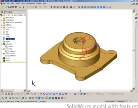
You read with 3DTransVidia native or neutral CAD files and transfer them to full feature based SW models. The feature based translation is semi-automatic. 3DTransVidia automatically splits the model into separate entities and categories them into two groups: free form object (NURBS) and analytical objects (PLANE, CYLINDER, SPHERE, CONE, TORUS, SOR, EXTRUSION). The analytical objects having explicit representation in SW features are automaticaly translated. Other objects are translated with help of the user specifying desirable SW feature for each object.
You can cut the original model with 2D sections and use them as reference sketches in SW. Points lines and coordinate systems can be directly transferred toform references for your design in SW. 3D curves taken from the geometry can be used as 3D sketches for creation of SW features. The whole process is intuitive and fully interactive with drag & drop command. You simply take selected model entity from the 3DTransVidia window and drop it in the SW window.
 Rapid Reverse Engineering Module Rapid Reverse Engineering Module
Rapid Reverse Engineering Module provides tools for fully automatic reverse engineering process of objects defined as point clouds or polygon meshes into skins and solid compatible with SolidWorks.
Semi-Automatic and Manual Patch Generation
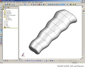
Semi-Automatic and Manual Patch Generation are organized in a logical workflow using one of the following strategies: curve network (curvature analysis), patch on geometry (multi-side patches) and polygon (set of cross-sections).
|

