3DTransVidiaby Capvidia
3DTransVidia is designed to repair 3D models created in different CAD systems. The repair process is automatic and can be applied to most complex 3D models and assemblies. The repair is always performed within the model tolerance maintaining the original model integrity and preventing model deformations. 3DTransVidia supports both native and neutral data formats.
CAD models often lack quality and precision required by the complex engineering processes (CAD -> CAE -> CAM). The geometrical and topological flaws are main obstacles in data translation. Complex CAD operations as model re-scaling, offsetting or Boolean operations are impossible to perform on invalid models. Repairs in native CAD system are in general difficult and time consuming as CAD system are not designed for this purpose.

3DTransVidia offers ultimate solutions to repair existing 3D CAD models to desired quality. Geometry check tools verify model compliance against the automotive industry standards as VDA 4955-2, JAMA and AIAG D-15 or user defined quality criteria.
The repair process consists of the following steps:
- data import
- tolerance control
- automatic repair & healing
- diagnostic & error classification
- manual repair
- quality check
- data export
Supported Data Formats (Import and Export):
- IGES
- VDA-FS
- STEP
- Parasolid
- CATIA v4
- CATIA v5
- CADDS (no export)
- ACIS
- Unigraphics (no export)
- RobCAD (no export)
- AutoForm
- STL
- VRML
Model Tolerance
3DTransVidia automatically finds the right model tolerance value by verifying the size of all model entities. The user controls the model tolerance by choosing between the following options:
- File tolerance (value stored in the file)
- Estimated tolerance (recommended default value)
- User defined tolerance (choice of the user)
Automatic repair
The automatic repair resolves over 60 typical geometry and topology conflicts. The repair is performed within a specified model tolerance without changing or deforming the original model. Even an inexperienced CAD user will complete the repair within very short time.
- Geometry Conflicts
- Invalid curve parameterization
- Gaps in composite curve
- Degenerative segments in poly-line
- NURBS improving simplification of curves
- Incorrect knots vector in the NURBS curve
- Topology conflicts
- Invalid edge vertices
- Invalid loop orientation in Parametric Space (PS)
- Missing loop definition in Model Space (MS)
- Missing loop definition in PS
- Invalid edge orientation
- Lack of loop synchronization between MS and PS
- Gaps in loop in MS, PS
- Not closed loop in MS, PS
- Self-crossing loop in PS
- Missing outer loop in face definition
- Wrong index of outer loop
- Invalid loop orientation
- Inconsistent face normal
Diagnostic and Error Qualification
3DTransVidia automatically classifies types of errors remaining in the model after automatic repair and suggests a most suitable manual repair workflow. Problematic places are visible in the project tree and remain there until they are fixed. The repair parts are automatically merged with the rest of the model.
The errors are classified into the following categories:
- Gaps
- Overlaps
- Untrimmed surfaces
- Self-intersecting
- Surfaces
- Open contours
Manual Repair
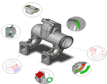
Manual repair has never been simpler. 3DTransVidia provides a workflow and special tools to easy and fast repair all remaining problems. Faulty places together with their neighbours are automatically isolated form the rest of the model. The user manipulates only on small part of the model instead of the whole model or complex assembly. There are specialized repair functions for fast and easy repair of the most complex problem.
- Gap diagnostics
- Open contour diagnostics
- Surface creation
- Surface recreation
- Surface merging
- Surface trimming
- Surface splitting
|

